Automatic Voltage Regulation for Transformers: OLTC and the REG-DA
How automatic voltage regulation on a tap-changed transformer works: setpoint, bandwidth, and time delay, tap-changer wear under IEC 60214-1, and parallel operation with the A.Eberle REG-DA.
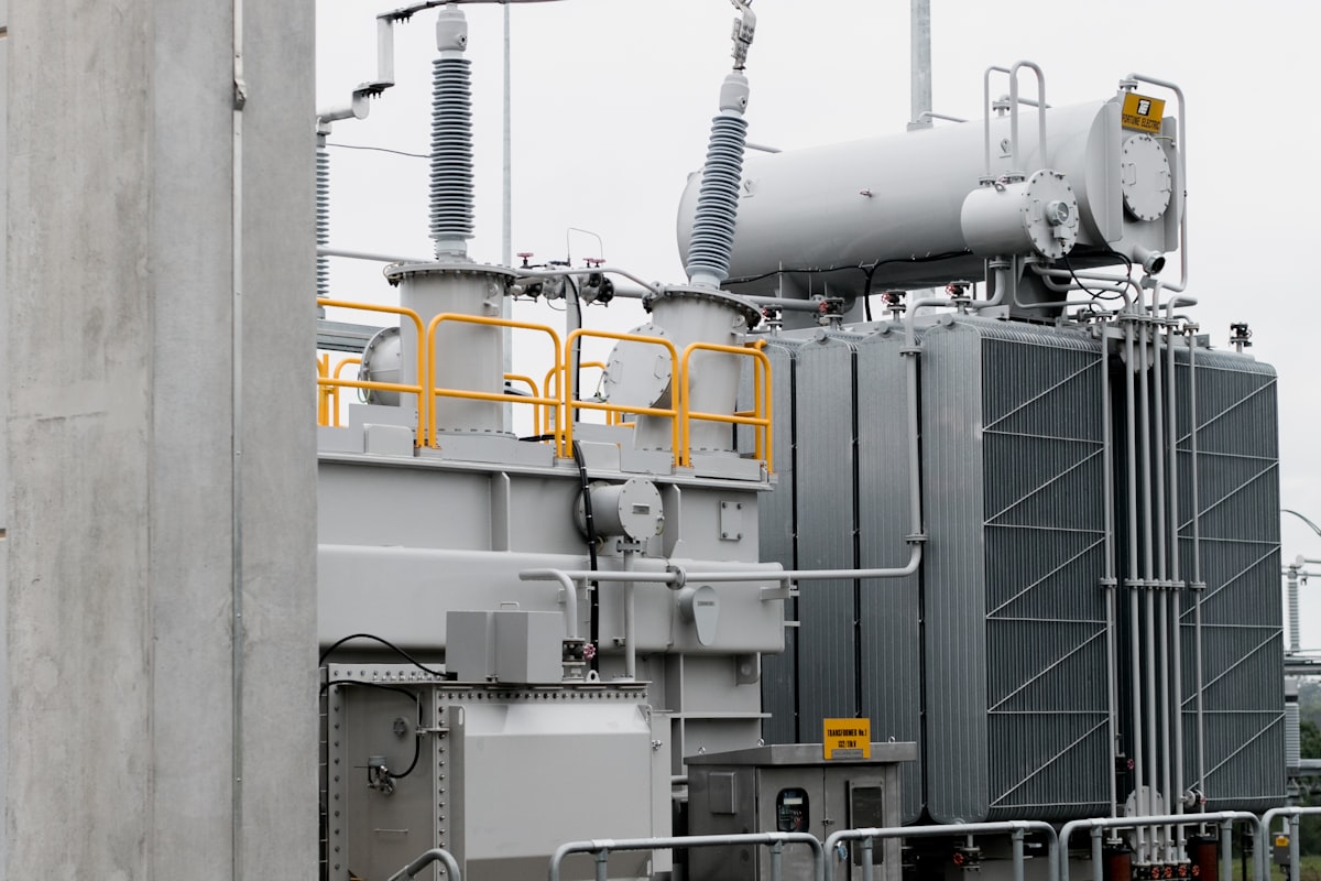
A distribution transformer's load swings across the day, and every swing drags the secondary voltage with it - low at evening peak, high at 3 a.m. The on-load tap changer (OLTC) exists to correct that by changing the winding ratio under load, and the automatic voltage regulator (AVR) is the device that decides when. Set it well and the network holds the EN 50160 voltage band [5] with a handful of tap operations a day; set it badly and the tap changer hunts itself toward its next overhaul.
A.Eberle builds the REG-DA, the transformer voltage regulator Pacific supplies in Pakistan, controlling single units and parallel groups of up to 15 transformers [1]. This guide covers the control loop, the three settings that decide its behaviour, and how parallel operation is kept from fighting itself.
What the Regulator Actually Controls (IEC 60214-1)
The control loop is short: measure the regulated voltage, compare it to the setpoint, and when the deviation persists, pulse the OLTC motor drive to raise or lower one tap. The tap changer itself - the diverter, selector, and motor drive - is governed by IEC 60214-1, the performance and test standard for on-load tap changers [3]. The regulator is the intelligence in front of it: the REG-DA takes the measurement, runs the decision, drives the mechanism, and doubles as transducer, recorder, and transformer monitor per IEC 60076 practice [1]. IEC/IEEE 60214-2 carries the application guidance for matching the tap changer to the duty [4].
The 3 Settings That Decide Everything
An AVR has one job and three parameters [2]:
- Setpoint - the target voltage at the regulated point, placed inside the statutory band with room for the load swing either side [5].
- Bandwidth - the dead band around the setpoint within which no action is taken. It must be wider than one tap step's voltage change: a bandwidth narrower than the step guarantees the correction overshoots the band and triggers the opposite correction - the hunting that wears a tap changer fastest.
- Time delay - how long a deviation must persist before the first tap command. Motor starts, cloud transients, and switching events pass in seconds; the delay filters them out so taps are spent on real load changes, not noise.
The three interact: a tight setpoint with a narrow band and a short delay reads as precision on paper and behaves as continuous mechanical wear in the field.
Tap-Changer Wear: Why Fewer Operations Matter
The OLTC is the only part of a power transformer that moves in normal service, and its maintenance schedule is written in operations, not years - contact wear and oil carbonisation track the operation counter. IEC 60214-1's endurance requirements are typed against defined operation counts [3], which makes the regulator a maintenance lever: every avoided unnecessary tap is deferred wear on the most maintenance-hungry component the transformer owns. A well-tuned REG-DA logging its own operation statistics [1] tells the asset engineer whether the settings are spending taps or saving them.
Parallel Transformers: 3 Ways to Keep Them From Fighting
Two transformers on one busbar with independent regulators will disagree - one taps up, the other sees the voltage rise and taps down, and a circulating reactive current flows between them, heating both and settling nothing. Parallel control exists to prevent exactly this [1]:
| Scheme | How it works | Where it fits |
|---|---|---|
| Independent regulators | each unit regulates alone | never for shared busbars; the fighting scheme |
| Master-follower | one regulator decides, others copy its tap | identical units on one busbar [1] |
| Circulating-current minimisation | each unit taps to minimise the reactive current between them | mixed units; REG-DA runs it with or without comms between controllers [1] |
The REG-DA handles groups of up to 15 transformers, detects the parallel configuration automatically, and its ParaGramer view maps the live switching state of each unit in single-phase representation [1] - the difference between a parallel scheme the operator can audit and one they discover during a trip.
Fitting Into the Substation: Comms and Monitoring
A regulator that cannot report is half a device. The REG-DA integrates into substation automation over IEC 60870-5-101/103/104, IEC 61850, and DNP 3.0 [1], so tap position, operation counts, and regulation state land in SCADA alongside the protection data. For the measurement side of the same connection point - harmonics, dips, and the EN 50160 evidence trail - the A.Eberle power quality analyzers guide covers the PQ-Box family that Pacific supplies from the same catalogue.
Common Specification Mistakes
The 5 recurring errors in voltage-regulation schemes:
- Bandwidth narrower than one tap step. The correction always overshoots and the scheme hunts; the band must exceed the step's voltage change [2].
- Time delay set at transient timescales. A delay short enough to chase motor starts spends the tap changer's IEC 60214-1 operation budget on events that would have passed anyway [3].
- Parallel units without a parallel scheme. Independent regulators on one busbar circulate reactive current between transformers; pick master-follower or circulating-current control [1].
- Regulating the busbar when the complaint is at the feeder end. The setpoint must represent where the voltage problem lives, or the regulation is precise at the wrong node [2].
- No operations counter in the maintenance plan. OLTC maintenance follows the counter, not the calendar [3]; a regulator that logs operations is the data source, if anyone reads it.
What to Specify When Enquiring: 6 Items
A voltage-regulation enquiry that quotes cleanly states:
- Transformer data - rating, ratio, and the OLTC's tap range, step voltage, and drive type per IEC 60214-1 [3]
- Single or parallel - group size and busbar arrangement; the parallel method follows from whether units are identical [1]
- Regulated point - transformer secondary or a downstream target the setpoint must represent
- Voltage band - the statutory or contractual limits the scheme must hold [5]
- Communications - IEC 61850, IEC 60870-5, or DNP 3.0, and what SCADA must see [1]
- Monitoring scope - whether the regulator also carries the transformer-monitoring and recording role [1]
Sourcing and Support in Pakistan
Pacific Engineering & Automation is the authorized A.Eberle reseller in Pakistan, supplying the REG-DA regulator and REGSys parallel-control systems alongside the EOR-D earth-fault relays and PQ-Box analyzers - for K-Electric and DISCO grid stations, industrial estates with captive distribution, and IPP substations. We help work through the settings, the parallel scheme, and the comms integration before the panel is wired.
To put disciplined voltage regulation on a tap-changed transformer, request a catalogue or quotation or contact our engineering team.
Field-derived case studies will be added to this post as Pacific Engineering & Automation accumulates engagement records. The current version is grounded in published specifications, regulatory documentation, and standards body references.
Sources
- A.Eberle REG-DA transformer regulator - product page: parallel operation, ParaGramer, protocols
- A.Eberle - Voltage Regulation - voltage regulation product family overview
- IEC 60214-1:2014 - Tap-changers, Part 1: Performance requirements and test methods
- IEC/IEEE 60214-2:2019 - Tap-changers, Part 2: Application guidance
- EN 50160:2022 - Voltage characteristics of electricity supplied by public distribution networks
Pacific Engineering & Automation
Need industrial equipment in Pakistan?
Authorized dealer and reseller for 16 international manufacturers. Karachi-based, serving Pakistan since 1995.