How to Locate an Underground Cable Fault, Step by Step
The field sequence for finding a buried cable fault: prove dead, trace the route, classify the fault per IEEE 1234, pre-locate with TDR or arc reflection, pinpoint, and identify before you cut.
Locating a buried cable fault is a fixed sequence, not an art: prove the cable dead, trace its route, classify the fault, pre-locate the distance, pinpoint the dig spot, and identify the cable before anyone cuts it. IEEE 1234-2019 codifies the techniques [1]; what follows is the field order they run in on an 11 kV feeder, and where each one goes wrong.
The previous cable fault location guide covered choosing between methods and Xi'an Huapu units; this one is the procedure itself, written for the crew standing at the tripped feeder.
Step 1: Isolate, Earth, and Prove Dead
Every fault-location method injects test voltage into the cable, so the sequence starts with switching: isolate both ends, apply earths, and prove dead at the test end before connecting anything. A faulted cable can hold charge, and a surge generator will later put kilovolts back onto it deliberately - the earthing discipline at both ends is what makes the rest of the procedure survivable. Remove the far-end earth only when the test plan requires it, and log who holds the keys.
Step 2: Trace the Route and Depth First
You cannot walk a fault you cannot follow. On networks where as-built drawings are decades old, an audio-frequency transmitter on the cable and a receiver above ground map the actual route and depth before any location work starts - the step that turns "somewhere under this road" into a line on the surface. Crews that skip it pre-locate a distance along a route they are guessing, then dig on the wrong side of the street. Route tracing and live/de-energised cable identification are what the HP-R30 class of detector exists for.
Step 3: Classify the Fault (IEEE 1234 Characterization)
An insulation-resistance measurement phase-to-phase and phase-to-sheath classifies the fault before any location method is chosen: a low-resistance fault or open-circuit break reads directly, a high-resistance fault holds off the megger, and an intermittent flashing fault reads healthy until voltage is raised. IEEE 1234-2019 builds its technique selection on exactly this characterization [1] - the classification decides the method, so five minutes with a megger saves an afternoon with the wrong instrument.
Step 4: Pre-Locate the Distance (TDR or Arc Reflection)
Pre-location gives the distance from the test end, and the fault class from Step 3 picks the tool [1][3]:
| Fault class | Pre-location method | Why |
|---|---|---|
| Low-resistance, breaks | TDR (low-voltage pulse) | reflection returns directly from the fault |
| High-resistance | Arc reflection (ARM) | surge ionises the fault; the arc reflects the TDR pulse [3] |
| Flashing, very long runs | Impulse current (ICM) | travelling-wave transit time gives the distance |
Two rules govern the step. First, the distance is only as accurate as the velocity factor entered for the cable's insulation type - XLPE and PILC propagate differently, and a wrong setting moves the fault tens of metres on the trace. Second, use the lowest surge voltage that produces a stable arc [3]; every unnecessary maximum-voltage shot ages the healthy cable either side of the fault.
Step 5: Pinpoint the Dig Spot (Surge and Acoustic)
Pre-location narrows an 800 m feeder to a zone of metres; pinpointing closes it to spade-width. The surge generator fires at intervals so the fault arcs underground, and the technician walks the zone with an acoustic sensor and electromagnetic frame: the EM pulse arrives effectively instantly, the ground-borne thump lags with distance, and the point where the two coincide is directly above the fault [3]. Digging on pre-location alone routinely misses by several metres - the acoustic walk is what pays for itself in one avoided wrong hole.
Step 6: Identify the Cable Before You Cut
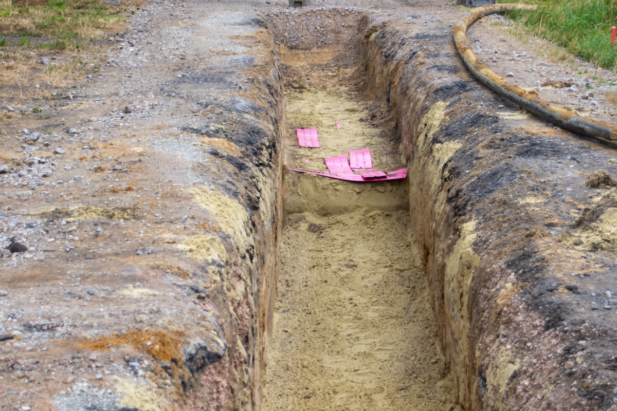
The trench at the dig spot rarely holds one cable. Before any cut or spike, the target cable must be positively identified against its neighbours - with an identification signal on de-energised cable, or a live-cable identifier where adjacent circuits stay energised. Cutting an unidentified cable is the worst outcome available in this procedure: it creates a second outage on a healthy feeder and puts the crew on a live conductor. The identification step is procedural, not optional, and it is the reason cable identifiers ship alongside route tracers.
Step 7: Test Before Re-Energising (IEEE 400)
After the repair, the joint and the disturbed cable earn a field test before the feeder carries load again. IEEE 400-2012 is the umbrella guide for field testing shielded power cable insulation [2] - an insulation-resistance check at minimum, a withstand or diagnostic test where the asset matters. Re-energising an untested repair converts a planned outage back into an unplanned one, on the same feeder, with the same customers watching.
Common Field Mistakes
The 5 that recur across fault-location work [1][3]:
- Digging on pre-location alone. The distance is a zone, not a spot; skipping the acoustic walk misses by metres.
- Locating along an untraced route. A perfect distance along a wrong route line is a wrong hole with confidence.
- A default velocity factor. The TDR reads time; the operator supplies the geometry. Wrong factor, wrong street.
- Maximum surge voltage by habit. The arc needs stability, not spectacle [3]; excess voltage stresses the healthy cable and the joints that survived.
- Cutting before identifying. One unidentified cut can outage a second feeder and endanger the crew; identification is part of the dig, not an extra.
The Kit: 5 Items
The procedure maps onto five pieces of equipment - a multi-pulse fault tester for TDR and impulse methods (HP-A30 class), an HV surge generator for arc reflection and pinpointing (HP-G35 class), the acoustic and EM pinpointing set, a route tracer and cable identifier (HP-R30 class), and the earthing and PPE that Step 1 assumes. Utilities running daily fault work consolidate all of it onto the HP-A40 van or HP-A50 trolley platforms; the cable fault location methods guide covers that fleet decision.
Sourcing and Support in Pakistan
Pacific Engineering & Automation is the authorized Xi'an Huapu reseller in Pakistan, supplying the fault-location range from portable testers to integrated vans for K-Electric, DISCO, and industrial-estate cable networks - with method training and velocity-factor calibration support from our Karachi office, so the sequence above runs the same way on the fifth fault as on the five-hundredth.
To equip a fault-location crew, request a catalogue or quotation or contact our engineering team.
Field-derived case studies will be added to this post as Pacific Engineering & Automation accumulates engagement records. The current version is grounded in published specifications, regulatory documentation, and standards body references.
Sources
- IEEE 1234-2019 - IEEE Guide for Fault-Locating Techniques on Shielded Power Cable Systems
- IEEE 400-2012 - IEEE Guide for Field Testing and Evaluation of the Insulation of Shielded Power Cable Systems Rated 5 kV and Above
- Electric Energy Online - Underground Cable Fault Locating Using the Arc Reflection Method
Pacific Engineering & Automation
Need industrial equipment in Pakistan?
Authorized dealer and reseller for 16 international manufacturers. Karachi-based, serving Pakistan since 1995.